RS-422 to RS-485 converter
Helen Li
SMQT
2016-06-03 17:11:24
RS-422 to RS-485 converter
Data Transmission Signals
Unbalanced Line Drivers
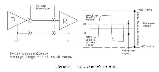
Each signal that transmits in an RS-232 unbalanced data transmission system appears on the interface connector as a voltage with reference to a signal ground. For example, the transmitted data (TD) from a DTE device appears on pin 2 with respect to pin 7 (signal ground) on a DB-25 connector. This voltage will be negative if the line is idle and alternate between that negative level and a positive level when data is sent with a magnitude of ±5 to ±15 volts. The RS-232 receiver typically operates within the voltage range of +3 to +12 and -3 to -12 volts as shown in Figure 1.1.


Balanced Line Drivers
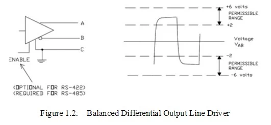
In a balanced differential system the voltage produced by the driver appears across a pair of signal lines that transmit only one signal. Figure 1.2 shows a schematic symbol for a balanced line driver and the voltages that exist. A balanced line driver will produce a voltage from 2 to 6 volts across its A and B output terminals and will have a signal ground (C) connection. Although proper connection to the signal ground is important, it isn't used by a balanced line receiver in determining the logic state of the data line. A balanced line driver can also have an input signal called an “Enable” signal. The purpose of this signal is to connect the driver to its output terminals, A and B. If the “Enable” signal is OFF, one can consider the driver as disconnected from the transmission line. An RS-485 driver must have the “Enable” control signal. An RS-422 driver may have this signal, but it is not always required. The disconnected or "disabled" condition of the line driver usually is referred to as the “tristate1” condition of the driver. 1 The term “tristate” comes from the fact that there is a third output state of an RS-485 driver, in addition to the output states of “1” and “0.”


